PRELIMINARY DESIGN OF SHELLS
The principal purposes for preliminary design of any structure is: (1) To obtain quantities of materials for making estimates of cost. (2) Obtain a clear picture of the structural action, (3) Establish the dimensions of the structure, and, (4) Use the preliminary design as a check on the final design.
It is not expected that these preliminary design calculations be precise, but rather they should be within an accepted tolerance. The worst way to start a design is to immediately set up a finite element analysis. Any new type of structure requires an extended lead time to obtain a thorough understanding of the structural action.
The discussion of preliminary analysis here, has been restricted to principals rather than to presentation of calculations. Given these principals, the engineer should be able to set up his own calculations. Do not try to design shells without a thorough study of the relevant sections of the current American Concrete Association regulations. There are differences from the normal structures.
Thickness of shells
The thickness of the slab elements are normally governed by the number of layers of reinforcing bars. For shells of double curvature, there are usually only two layers so the minimum thickness could be:
Two 3/8 in. bars, two 1/2 in. of cover equals 1.75 inches.
However a little tolerance should be added. For a barrel shell or a folded plate:
Two 1/2 in. bars, one 3/4 in. bar, two 1/2 in. of cover equals 2.75 in.
Of course, the concrete stresses should be checked, but they seldom control. Do not think that a shell will be stronger if it is thicker than required.
For a description of the structural elements of the shells discussed here, the reader should first study the presentations in Mark Ketchum's Types and Forms of Shell Structures
Preliminary Design for Types of Shells
Barrel Shells
Folded Plates
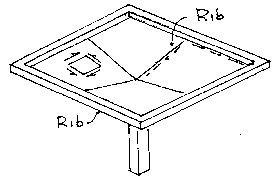
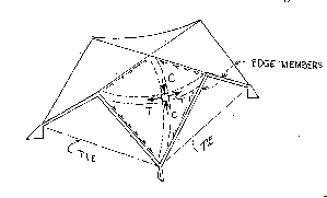
Umbrella Shells
Four Gabled Hypars
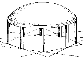
Domes of Revolution
Translation Shells
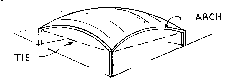
BARREL SHELLS
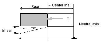
First find the longitudinal and shear (diagonal tension) reinforcing required for a typical interior element of the structure.
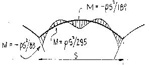
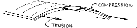
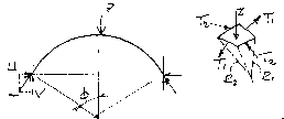
1. A barrel shells acts as a beam in the long direction and as an arch in the curved area. The arch is supported by internal shears. Approximate values for the bending moments in the arch are summarized in the following sketch.
If there are no other forces on an element at the neutral axis of the beam, then the diagonal tension equals the shear. From this information, a pattern of diagonal tension bars can be constructed.
5. The horizontal reaction of the arch elements of the shell must be contained by an rigid frame and a horizontal tie. Assume that this is simply a wide arch equal to half of the span. An approximation for the horizontal force would be equal to the load per foot on this arch times the arch span, squared divided by 8 and the rise. The thrust in the arch can be determined from this and the vertical reaction.
6. The edge spans of the shell should be supported by intermediate columns. The stiffness of a barrel shell at the outside edges is simply not stiff or strong enough to carry the required loads. The shell reinforcing at the edge members acts more like a typical arch and should be reinforced with two layers of bars.