INTERESTING POSSIBILITIES FOR SHELL STRUCTURES
There are several types of shell structures that offer advantages in terms of utility and cost and perhaps in aesthetics.
LONG SPAN DOMES
Constructions of spherical domes by using inflated membranes as forms has proven to be a viable solution to many problems. The largest shells constructed are now less than 300 feet in diameter. Some uses, such as sports facilities demand greater spans, perhaps as much as 1000 feet. The design and construction of such a shell is a challenge, and using inflatable forms and a uniform depth may not be possible. For very large spans, a grid constructed with pans is necessary so that the dome will be stiff enough and still weigh less than a uniform depth.
The construction of this structure will require the greatest ingenuity. One method will be to construct the dome by a form on a track that moves around the inside of the dome, placing concrete at a short horizontal and vertical section, and then moving around to place the next section. After each circle is completed, then the rig would be raised, and the ring above placed. The grid could be formed by using semirigid insulation thus ensuring acoustical treatment
VAULTS
A vault may be defined as a single barrel shell, supported on its side by walls or columns. The virtue of the vault is that half of the load on the shell is carried by the walls, and the other half is carried to the ends and at that point the usual arch and tie are required. The thickness of a shell can be much less that for a normal arch of the same span because the shell carries loads as a space structure.
This structural system can be used, for example, for sports facilities with widths up to 300 feet and lengths to 500 feet. These spans will require a ribbed structure created by pans or insulating blocks of foam set on the forms. Again ingenuity will be required for maximum economy.
FOLDED PLATE
The usual folded plate structure, has been constructed with two or three element folded plates, with slopes of slightly less than 45 degrees, and tied at the ends by frames and horizontal ties. A much more interesting system is to use plates with much less slope and use vertical columns for end support rather than the usual ties. The spans of the slab elements can be of relatively long, (25 to 30 feet), if the slabs are haunched. The optimum distance valley to valley would then be, say, 50 ft., and the span of the folded plates, 50 ft. with a height of 5 ft. The slope of the slabs is the a ratio of 1 to 5. The concrete would be much easier to place than The usual steep slope, thus leading to better economy. In my opinion the shape would be more esthetically interesting, leading to a de-emphasis of the repetitious nature of some folded plate structures.
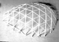
FUNICULAR SHELLS
A dome of any size or shape can be designed for any plan by using the differential equation of a bubble. Finite differences are used to solve the equations. The photo shows a stick model of a tear drop shaped dome. The construction of this model
was possible because the dimensions were generated by the program.
I have written a paper on "Funicular Frame Works" which shows how to generate and solve the equations. It is available by sending me an Email.
SHELL ARCHES
A shell arch has a longitudinal cross section of a barrel shell or a folded plate, but is a circular arch or other shape in profile. This arch is suitable for extremely long spans, say to 1000 feet, and is one of the most efficient structural systems possible. To put it another way, there will be less concrete in the roof than in the floor system, and the reinforcing will be minimum
The most interesting aspect of the design is the selection of the forming system. The usual method would be to use a curved form moving on a track that would form two or three units, and then decenter, move to the next set of shells, recenter and cast the next unit. The decentering of such a large structure for would be a real chore and would require expensive manual or hydraulic jacks. My idea is to form the final curves with air inflated bags, then the bags could be deflated to move to the next placement, and the massive forms would not need to be decentered. This type of structure deserves further study.
|